If you have spent any time browsing TFT LCD module specifications, you have probably seen “RGB interface” listed as the electrical interface. It is one of the most common display interfaces in the 3.5-inch to 7.0-inch range, yet many engineers get tripped up by what it actually requires from the host system. Unlike SPI or MCU interfaces, an RGB interface does not have a frame buffer on the display side. That single difference shapes everything: which MCU or MPU you need, how you route your PCB, and whether the design will even work at all.
This article explains what an RGB interface actually is, how its signals work, how it compares to MCU and LVDS interfaces, and which CDTECH TFT modules are available with parallel RGB. By the end, you will know whether an RGB interface is the right choice for your design or whether you should be looking at LVDS instead.
What Is an RGB Interface? The Parallel Approach to Display Data
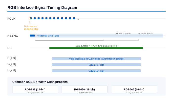
An RGB interface, sometimes called parallel RGB, TTL RGB, or DPI (Display Parallel Interface), is a digital display interface that transmits pixel color data over parallel data lines. For a standard 24-bit configuration, that means 8 lines for red, 8 for green, and 8 for blue, a total of 24 data lines, plus at least 4 synchronization signals: HSYNC, VSYNC, DE (Data Enable), and PCLK (Pixel Clock).
Here is the key distinction that separates RGB from interfaces like MCU or SPI: an RGB display has no internal frame buffer, or GRAM. The display does not remember a single pixel. You, or rather your host processor, must send every pixel of every frame, continuously, at the refresh rate the panel expects. If you stop sending data, the screen goes blank or freezes on the last received line. Think of it like a CRT monitor: the host is responsible for generating the video stream, and the panel simply displays whatever arrives in real time.
MCU and SPI interfaces, by contrast, send commands and pixel data to a GRAM inside the display driver IC. The display controller handles panel refreshing internally. That means you can update only the pixels that changed and leave the rest alone. This is easier on the MCU but much slower for full-screen animation or video. The RGB interface trades MCU overhead for raw bandwidth: it can push entire frames at 60 Hz without breaking a sweat, but the host processor must be capable of generating a real-time video signal.
RGB Interface Signal Lines: HSYNC, VSYNC, DE, and PCLK
Every parallel RGB interface relies on a common set of timing and data signals. Understanding these is critical for debugging during board bring-up, because one misconfigured timing parameter can leave you staring at a blank screen.
Data lines (R[7:0], G[7:0], B[7:0]): These carry the pixel color values. A full 24-bit configuration uses all 24 lines and can display 16.7 million colors. Many designs reduce the pin count by using lower bit depths:
- RGB888 (24-bit): 8 bits per color channel, 16.7M colors. Uses all 24 data lines.
- RGB666 (18-bit): 6 bits per color channel, 262K colors. Uses 18 data lines. The lower 2 bits per channel can be tied to GND or left floating.
- RGB565 (16-bit): 5 bits for red, 6 for green, 5 for blue, 65K colors. Uses 16 data lines. Very common in embedded systems where pin count is tight.
PCLK (Pixel Clock): One pixel of data is transferred on each rising or falling edge of this clock. The required PCLK frequency is calculated as: PCLK = Total_Horizontal_Pixels x Total_Vertical_Lines x Refresh_Rate. For an 800 x 480 display at 60 Hz with blanking, you may need around 25 to 33 MHz, well within the capability of most embedded MPUs.
HSYNC (Horizontal Sync): Marks the end of each line. After the last pixel of a line, the controller issues an HSYNC pulse, and the display resets its column pointer to the left edge, ready for the next line.
VSYNC (Vertical Sync): Marks the end of each frame. After the last line of a frame, the controller issues a VSYNC pulse, and the display resets its row pointer to the top.
DE (Data Enable): Some panels use DE mode instead of or in addition to HSYNC/VSYNC. DE is active-high during the active pixel region and low during blanking intervals. Many embedded designs prefer DE mode because it simplifies the timing controller configuration.
RGB vs. MCU vs. LVDS: Which Interface Fits Your Design
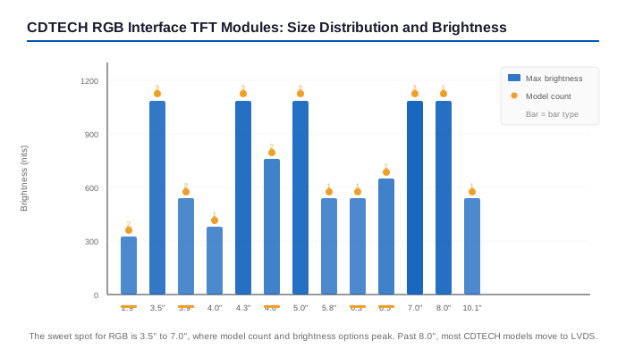
Choosing between RGB, MCU, and LVDS comes down to four factors: the size of your display, the distance between the board and the panel, the capability of your host processor, and how much EMI margin your product has. Here is a practical comparison:
| Feature | RGB (Parallel) | MCU (8080/6800) | LVDS |
|---|---|---|---|
| Signal Type | Parallel TTL (24-28 lines) | Parallel with read/write control | Serial differential pairs |
| Typical Wire Count | 20 to 28 signal lines | 12 to 16 signal lines | 4 to 8 signal lines (1-2 pairs + CLK) |
| Max Cable Length | 15-20 cm (limited by skew and EMI) | 20-30 cm | 1-5 meters |
| Typical Resolution | Up to 800×480, some 1024×600 | Up to 480×320 | Up to 1920×1080 |
| Frame Buffer | In host RAM only | In display GRAM (driver IC) | In host RAM only |
| Host Requirement | Needs LCD controller (MPU or advanced MCU) | Any MCU with GPIO or FSMC | Needs LVDS transmitter or SoC with LVDS output |
| EMI Performance | High: 24 lines switching simultaneously | Moderate | Low: differential signaling cancels radiation |
| Best For | Compact embedded HMI, IoT panels, handheld devices | Simple instrument displays, low-res GUIs | Industrial control panels, vehicle dashboards, long cable runs |
| Typical CDTECH Size Range | 2.9″ to 10.1″ | 1.9″ to 4.3″ | 5.0″ to 15.6″ |
Here is a simpler way to think about it. If your display is under 4.3 inches and the GUI is basic, MCU is often sufficient and easier to design with. If you are in the 3.5 to 7.0 inch range, need smooth 60 Hz animation, and your processor has an LCD controller, the RGB interface is the pragmatic choice: it is fast, direct, and well-supported by the embedded ecosystem. If your display is larger than 7 inches, your cable run is longer than 20 cm, or you need to pass EMC certification for a vehicle or medical product, use LVDS. The differential signaling in LVDS solves noise problems that become real headaches with parallel RGB at longer distances.
CDTECH RGB Interface TFT LCD Modules by Size
At CDTECH, the team I work with offers a broad range of TFT LCD modules with RGB interface, spanning from compact 2.9-inch bar-type displays to a 10.1-inch panel. All models are IPS or TN technology with standard or industrial temperature grades. Here is the full lineup:
| Size | Model | Type | Resolution | Brightness | Temp Range | Notes |
|---|---|---|---|---|---|---|
| 2.9″ Bar | S029HQ05NS | IPS | 320×120 | 300 nits | -20/70°C | Bar type |
| 2.9″ Bar | S029GQ07NS | TN | 320×120 | 300 nits | -20/70°C | Also supports SPI/MCU |
| 3.5″ | S035GQ09NS/HS/ES | TN | 320×240 | 350/500/800 nits | -20/70°C | 3 brightness tiers, also SPI/MCU |
| 3.5″ | S035HQ55NS/HS/ES | IPS | 320×240 | 350/500/1000 nits | -20/70°C | Up to 1000 nits sunlight readable |
| 3.5″ | S035CHV85EN | IPS | 320×480 | 700 nits | -20/70°C | Portrait orientation |
| 3.9″ Bar | S039QWQ01HS | TN | 480×128 | 500 nits | -20/70°C | Bar type |
| 3.9″ Bar | S039HWQ12HS | IPS | 480×128 | 500 nits | -20/70°C | Wide viewing angle bar |
| 4.0″ | S040HWV08NN | IPS | 480×480 | 350 nits | -20/70°C | Square format |
| 4.3″ | S043HWQ50HG/EG | IPS | 480×272 | 500/1000 nits | -30/85°C | Industrial temp, sunlight option |
| 4.3″ | S043HWV94NS/HS/ES | IPS | 800×480 | 350/500/1000 nits | -30/85°C | Wide temp, 3 brightness options |
| 4.3″ Bar | S043HWV104EN | IPS | 800×130 | 800 nits | -20/70°C | Bar type, high brightness |
| 4.6″ Bar | S046QWV11HS | TN | 800×320 | 550 nits | -20/70°C | Bar type |
| 4.6″ Bar | S046HWV14EA | IPS | 800×320 | 700 nits | -20/70°C | Wide viewing angle bar |
| 5.0″ | S050BWV105ES | IPS | 800×480 | 1000 nits | -30/85°C | Industrial temp, sunlight readable |
| 5.0″ | S050HWV18NS/HS/ES | IPS | 800×480 | 350/500/1000 nits | -20/70°C | 3 brightness tiers |
| 5.0″ | S050QWQ06NG/HG/EG | TN | 480×272 | 300/500/950 nits | -20/70°C | Budget-friendly option |
| 5.8″ | S058HWV08HS | TN | 800×320 | 500 nits | -20/70°C | Mid-size widescreen |
| 6.3″ Bar | S063BWV01HN | IPS | 800×280 | 500 nits | -20/70°C | Bar type |
| 6.5″ Bar | S065BWS07HG | IPS | 1024×400 | 600 nits | -20/70°C | Higher-res bar type |
| 7.0″ | S070SWV49NG/HG/EG | TN | 800×480 | 350/700/1000 nits | -20/70°C | Popular 7″ platform |
| 7.0″ | S070QWV75ND | TN | 800×480 | 350 nits | -30/85°C | Wide industrial temp |
| 7.0″ | S070SWV169ED | IPS | 800×480 | 1000 nits | -20/70°C | Dual-mode: RGB and LVDS |
| 8.0″ | S080QSV26EA | TN | 800×600 | 1000 nits | -20/70°C | 4:3 ratio, high brightness |
| 10.1″ | S101QWS68HD | IPS | 1024×600 | 500 nits | -20/70°C | Largest RGB model |
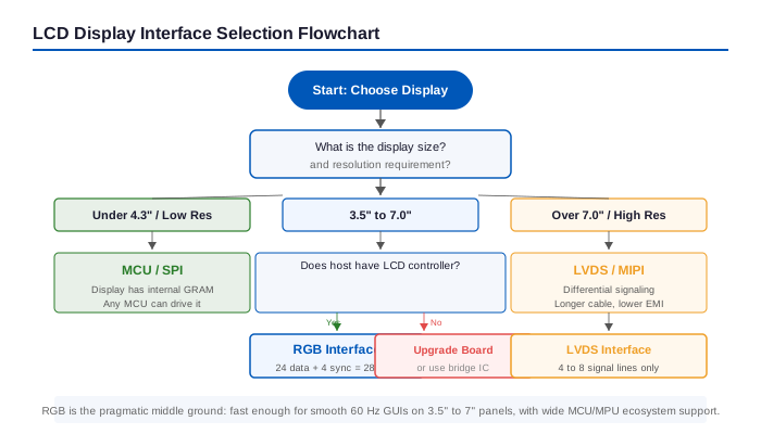
As you move through the table, notice that the sweet spot for the RGB interface is the 3.5 to 7.0 inch range. Once you go above 7.0 inches, most of our products move to LVDS, with only the S080QSV26EA and S101QWS68HD staying on RGB. That is intentional: parallel RGB becomes harder to manage at higher resolutions due to pin count and signal integrity.
Practical Design Considerations for RGB Interface
PCB Layout and Signal Integrity
Twenty-four data lines switching simultaneously at 25 to 33 MHz is a recipe for radiated emissions. A few layout habits will save you from failing EMC testing on the first pass:
- Keep RGB trace lengths matched, especially the data lines relative to PCLK. A skew of more than 1 to 2 ns between clock and data can cause sampling errors at the panel end.
- Use a solid ground plane under the RGB traces. Do not route them across a split in the plane or near a switching power supply.
- Add series termination resistors (22 to 33 ohms) at the source end of each data line to reduce overshoot and ringing.
- If your panel is on a separate board connected via a ribbon cable, interleave ground wires between groups of data lines, for example, GND-R7-R6-R5-R4-GND-R3-R2-R1-R0-GND, to minimize crosstalk.
Cable Length Limits
The practical limit for parallel RGB over a standard FFC or FPC cable is about 15 to 20 cm. Beyond that, skew between the clock and data lines becomes uncontrollable, and the cable starts acting as an antenna. If your mechanical design forces a longer run, do not try to brute-force RGB. Switch to LVDS, where differential signaling easily handles meter-long cables with far less EMI.
Refresh Rate Calculation
To verify your PCLK is fast enough, use this formula:
PCLK = H_total x V_total x Refresh_Rate
Where H_total includes the active horizontal pixels plus horizontal back porch, front porch, and sync width. For a typical 800 x 480 panel at 60 Hz with standard blanking intervals, H_total is around 1056 and V_total around 525. That works out to about 33.3 MHz. If your LCD controller tops out at 25 MHz, you may need to drop to 50 Hz or choose a panel with smaller blanking intervals.
Power Sequencing
RGB display modules usually have separate power rails for the logic (VCC, typically 3.3V) and the backlight (VLED, anywhere from 9V to 20V depending on the LED string configuration). Power them up in the right order: VCC first, then the RGB signals (which can be driven high-Z or with valid data), then the backlight. Failing to sequence correctly can cause a white flash at boot or, in extreme cases, latch-up damage to the driver IC.
When to Move from RGB to LVDS
If you are using an RGB interface successfully and your product works, there is no reason to change. But here are the signs that you may have outgrown parallel RGB and should start looking at LVDS:
- Your resolution target is above 1024×600. The PCLK for 1280×800 at 60 Hz pushes past 70 MHz, where parallel TTL signals get ugly without careful termination and equalization.
- Your cable between the board and the display exceeds 20 cm. LVDS was designed for exactly this problem.
- You are going through EMC pre-compliance and the RGB bus is your top emitter. Switching to LVDS can drop radiated emissions by 10 to 15 dB with no other changes.
- You simply do not have 28 spare GPIOs on your processor and pin-muxing is becoming a nightmare. A 4-wire LVDS link (1 clock pair + 3 data pairs for single-link) frees up a lot of pins.
Some CDTECH modules, like the S070SWV169ED, support both RGB and LVDS on the same panel, which makes for a clean migration path: design one board with LVDS, use the same panel during development in RGB mode, and switch to LVDS for production.
Frequently Asked Questions
My MCU does not have an LCD controller. Can I still use an RGB interface display?
No, not directly. An RGB interface requires the host to generate a continuous video signal with HSYNC, VSYNC, DE, and PCLK. Standard microcontrollers like STM32F4 or PIC32 do not have this peripheral. You have three options: switch to an MCU that does have an LCD controller (like the ESP32-S3, STM32F7 with LTDC, or many NXP i.MX RT parts), add an external RGB-to-LVDS bridge chip that also handles timing generation, or switch to an MCU interface display that has its own GRAM and does not need a host-side controller.
What is the maximum resolution I can drive with an RGB interface?
In practice, about 1024×600 at 60 Hz, which requires a PCLK of roughly 50 to 55 MHz. Above that, signal integrity on a parallel bus becomes a real problem. Some application processors can push 1280×800 over parallel RGB, but you will need very tight layout, series termination, and likely a shorter cable than what a typical product allows. For resolutions of 1280×800 and above, LVDS or MIPI DSI is the standard choice.
Can I convert an RGB output to LVDS or vice versa?
Yes, and this is actually a common design pattern. Dedicated bridge ICs like the TI SN75LVDS83B or the Toshiba TC358762XBG convert parallel RGB to LVDS (transmitter side), while devices like the TI DS90CF386 convert LVDS back to parallel RGB (receiver side). These bridges are transparent: you configure your LCD controller for RGB timing, and the bridge serializes the data into LVDS pairs. CDTECH also offers adapter boards that handle this conversion for customers who want to use an RGB-capable MPU with an LVDS panel.
Why does my RGB display flicker or show tearing?
Flickering on an RGB display usually comes down to one of three things. First, check PCLK polarity: some panels sample on the rising edge, others on the falling edge, and getting this wrong causes mis-sampled pixels. Second, verify your blanking timing parameters (front porch, back porch, sync width) match the panel datasheet exactly; approximate values from a similar panel rarely work. Third, if you see tearing rather than random flicker, your frame buffer is likely being updated while the LCD controller is reading it. Enable vsync-synchronized buffer swapping in your graphics stack, or use a double-buffered approach.
RGB565 vs RGB888: when does the color difference actually matter?
For industrial HMIs, instrument panels, and most embedded GUIs, RGB565 (65K colors) is perfectly adequate and saves 8 GPIO pins. The human eye can barely distinguish the missing color depth on a 5- or 7-inch panel at normal viewing distance. RGB888 (16.7M colors) matters when your UI includes smooth photographic gradients, when you need accurate brand colors, or when the display is large enough (above 8 inches) that banding in RGB565 becomes noticeable. One pragmatic approach: design your PCB to support RGB888 but populate only the upper 5/6/5 bits during prototyping. If color banding bothers you, add the remaining 8 lines in the next board spin.
Working on a design that needs an RGB interface TFT module? The team I work with at CDTECH offers over 20 models with parallel RGB, from 2.9-inch bar displays to 10.1-inch panels, with brightness options up to 1000 nits and industrial temperature ranges down to -30 degrees C. Custom FPC length, connector orientation, and touch panel integration are all on the table. Reach out to [email protected] and I will help you find the right fit.

 English
  Español
  日本語
日本語  한국어
한국어
Leave a Reply