Here is a situation I see regularly. An inquiry arrives, listing the display size and resolution. A 7-inch, 1024×600. Or a 4.3-inch, 480×272. The interface field is blank. The sender has not specified RGB, MIPI, LVDS, or SPI.
Is this a gap in their homework? I do not think so. It is the normal starting point of an LCD interface selection conversation. The interface is not something the customer should arrive with. It is something the two sides figure out together, starting from constraints on both ends.
This article walks through how LCD interface selection actually works in practice: not by comparing specs and declaring a winner, but by matching what the customer’s mainboard can drive with what the supplier’s driver IC and module design can support.
Why “Which Interface Is Better” Is the Wrong Question
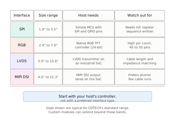
Before we go further, a quick orientation on the four interfaces you are most likely to encounter in the 2.4-inch to 15.6-inch TFT LCD range:
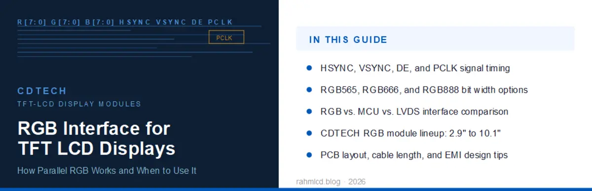
- RGB: A parallel interface. Red, green, and blue color data travel over 18 or 24 dedicated data lines depending on color depth, synchronized by HSYNC, VSYNC, and DOTCLK signals. Common in small-to-mid sizes (2.4-inch through 7-inch). Simple protocol, cost-effective, but requires a host with a native RGB TFT controller and uses more connector pins than serial alternatives. See our RGB Interface article for a deeper dive.
- MIPI DSI: A serial interface using differential signaling. Low pin count, low power, suited to compact designs and high-resolution panels. Common in newer embedded designs. Our MIPI Display Module Guide covers the details.
- LVDS: Differential signaling designed for longer cable runs and noise immunity. The industrial workhorse from 5-inch through 15.6-inch panels. See the LVDS Display Module Guide for specifications.
- SPI: Low pin count, common for small displays (2.4-inch to 3.5-inch) and simple MCU-driven setups. Requires writing initialization register sequences, which adds firmware effort.
Customer-Side Constraints: What Your Side Decides
Before looking at what a supplier can offer, start with your own side. Three things usually determine the feasible set of interfaces.
Host/Mainboard Capability
This is usually the hardest constraint. If your MCU has a native RGB TFT controller with a 24-bit parallel output, you are in RGB territory. If your SoC exposes a MIPI DSI lane, that opens MIPI panels. If you are working with a simpler MCU that only gives you SPI and a few GPIOs, SPI-driven displays with an onboard controller are your natural match.
Check your mainboard’s datasheet first. Not later. The interface options you can actually use are set here, and nothing the supplier does downstream can override a host that lacks the right controller or physical pins.
Your Team’s Development Capacity
Different interfaces demand different levels of firmware effort. SPI displays typically require sending a sequence of initialization registers to configure the display controller before the screen lights up. This is not difficult, but not every team has done it before. RGB and LVDS, by contrast, are more straightforward on the software side: configure the timing parameters, start sending frame data.
If your team has deep embedded experience, SPI is a non-issue. If firmware bandwidth is tight and you want the display to “just work” with minimal register-level configuration, RGB or LVDS may reduce your integration time.
Project Type Determines Flexibility
This is where the biggest fork happens in any LCD interface selection process.
New design or prototype stage: You have meaningful flexibility. You can follow the supplier’s IC-based recommendation. If the supplier’s standard module for your size comes in RGB and your host supports RGB, the decision is made and you move on.
EOL replacement project: Flexibility collapses. The original display’s interface pinout is already baked into your mainboard design. Changing the interface means changing the mainboard, which is rarely acceptable in an EOL replacement scenario. I wrote about this in detail in the LCD Display EOL Replacement guide. The core rule there applies here too: confirm the original interface pinout before doing anything else. If the EOL part used a 40-pin RGB interface, your replacement needs to match that, or you are looking at a board spin.
Supplier-Side Constraints: What the Module Decides
Now the other side of the equation. Even when you know what your host can drive, the display module itself has its own set of constraints. Understanding these helps you ask better questions when talking to a supplier.
Interface Comes from the Driver IC, Not the Glass
The LCD glass itself (the cell, the polarizers, the backlight) does not determine the interface. The driver IC mounted on the module’s flexible printed circuit does. The same glass can be paired with different driver ICs to produce modules with different interfaces. A 4.3-inch 480×272 panel is not inherently an RGB panel or an MCU panel. It depends on which IC the supplier selected and how that IC is configured. This trips up engineers who think about displays in terms of panel specifications, so it is worth stating explicitly early in the conversation.
Pattern A: One IC, Multiple Interface Modes via Configuration
A common pattern in the 2.4-inch to 3.5-inch range: a display built around a driver IC that supports multiple interface modes. For example, an IC primarily designed for SPI communication that can be reconfigured through register settings to operate in MCU 8080 parallel mode or RGB mode. The switching happens at the IC configuration level, not at the physical connector level. This gives the supplier the ability to offer the same glass in different interface variants for different customers.
Pattern B: Multiple Interfaces on One Connector, Selected by Hardware Pins
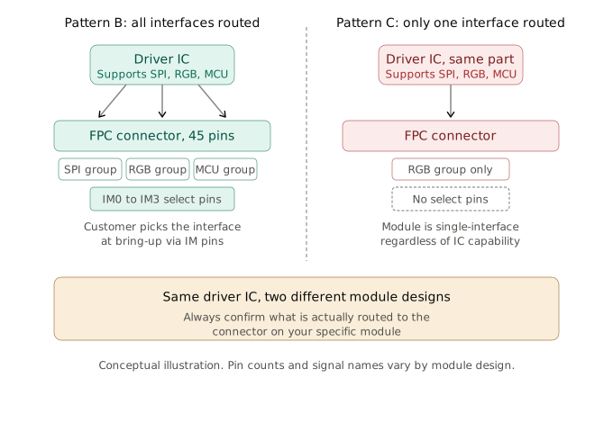
Pattern A above happens at the configuration level. The IC’s firmware or register settings decide the mode, but only one interface’s signals are physically brought out to the connector at a time. Pattern B goes a step further: the connector itself carries every supported interface’s signals simultaneously, and hardware pins alone decide which one is active. Take a 2.4-inch module whose FPC connector exposes all three interface signal groups on the same pinout:
- RGB signal group: VSYNC, HSYNC, DOTCLK, ENABLE, and 18 data lines (DB17 through DB0)
- SPI signal group: SDO, SDI, RD, WR/SCK, RS, CS
- Four IM (Interface Mode) select pins: IM0, IM1, IM2, IM3
All of these signals are present on a single 45-pin connector. The customer does not need to pick an interface at order time. They configure the IM pins via hardware pull-up or pull-down resistors at bring-up, and the driver IC boots into the corresponding mode. The switch from SPI to RGB to MCU mode is not a tooling change. It is not a different FPC. It is a hardware configuration on pins already present on the connector.
This matters because it means interface selection, in this scenario, is not even a procurement decision. It is a bring-up configuration, settled at the hardware design stage on the customer’s board.
Pattern C: The IC Supports It, But the Module Does Not Expose It
This is the distinction that causes the most confusion, and it deserves its own section.
A driver IC datasheet may list support for SPI, RGB, and MCU modes. That tells you what the silicon can do. It does not tell you what a specific module built around that IC actually makes available. Here is why.
When a supplier designs a module, they make a routing decision: which of the IC’s supported interface signal groups get traced out to the FPC connector, and which stay inside the chip, unconnected. Two modules built on the same IC can end up looking completely different from the customer’s side:
- All signal groups routed out: The supplier brings every supported interface’s signals to the connector, as in the Pattern B example above. The customer gets to choose at bring-up.
- Only one signal group routed out: The supplier routes, say, only the RGB data and timing lines to the connector, even though the IC underneath also speaks SPI and MCU. The unused signal pins on the IC are either pulled to a fixed level or left floating internally. They were never brought to the connector.
In case (2), the module is single-interface from the customer’s perspective. It does not matter what the IC datasheet says about multi-interface support. The SPI and MCU modes are electrically inaccessible because the traces that would carry those signals do not exist on the FPC.
When the Interface Cannot Be Changed
Some situations leave no room for reconfiguration. The driver IC may be factory-configured to one interface mode with no hardware pins to switch it. The panel’s glass routing may have been designed for one interface’s specific signal requirements, and changing the interface would require re-spinning the cell layout. At that point, the options narrow to three: change the driver IC (a customization project), change the mainboard on your side, or find a different supplier whose standard module already matches your interface. If customization is the path forward, our Custom LCD Display OEM guide covers what to evaluate before committing to a supplier.
A Practical Decision Framework
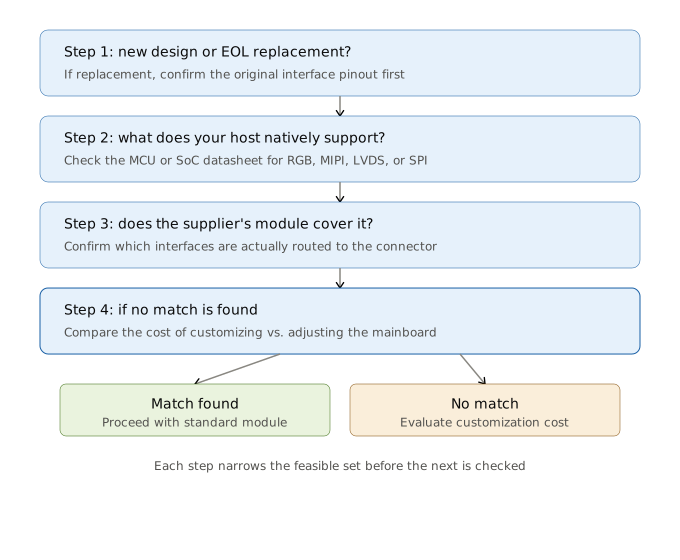
With the constraints from both sides on the table, here is the LCD interface selection sequence I recommend. This is not a comparison table. It is a decision flow.
- New design or replacement? If replacement, confirm the original interface pinout first. Everything downstream depends on this answer.
- What does your host natively support? Check the datasheet. Does the MCU or SoC expose an RGB controller, MIPI DSI lanes, LVDS transmitter, or only SPI/GPIO? The answer sets the feasible set.
- Can the supplier’s standard module for your size and resolution cover that? This is where you need to confirm not just what the driver IC is capable of, but which of those capabilities are actually routed to this specific module’s connector. Refer back to Pattern C: IC support and module support are not the same thing.
- If no standard module matches: Compare the cost of customizing the module (IC swap, FPC redesign) against the cost of adjusting your mainboard design. In most cases at the prototype stage, following the supplier’s standard option is cheaper.
What to Share With a Supplier Instead of Pre-Deciding an Interface
If you take one thing from this article, take this. When you reach out to a display supplier, you do not need to have already resolved RGB vs MIPI vs LVDS on your own. Trying to pre-decide the interface before understanding what the supplier’s modules actually offer can lead you to request a configuration that does not exist as a standard product.
Share two pieces of information instead:
- Your mainboard’s native interface capability: What does your MCU, SoC, or application processor output? Which interfaces does it support, and at what resolution?
- Whether this is a new design or a replacement: This tells the supplier how much flexibility exists on your side.
With these two data points, a supplier can usually confirm feasible options within a few days. The LCD interface selection becomes what it should be: a short conversation, not a research project.
Working on a project and need to figure out which display interface fits your mainboard? Share your host’s native interface capability and whether this is a new design or a replacement, and I can help you get a feasibility read. Contact: [email protected]
Related Reading
Frequently Asked Questions
I know my resolution and size but not the interface. Is that a problem when contacting a supplier?
No, it is completely normal. Most inquiries at the prototype stage arrive without a specified interface. Share your mainboard’s native interface capability and whether this is a new design or a replacement project. The supplier can then confirm which interface options are feasible from their side. Interface selection is usually a conversation, not a prerequisite.
Can I switch interfaces later in development?
It depends on your project type. On a new design at the prototype stage, switching interfaces is often feasible if the supplier’s module supports it (see Pattern B and C in the article). On an EOL replacement project, the interface is typically locked because your mainboard was designed for the original pinout. Changing the interface in that case means changing the mainboard, which is rarely acceptable.
If an IC datasheet says it supports MIPI and RGB, does that mean any module using that IC gives me both options?
Not necessarily. This is the distinction covered in Pattern C of the article. The IC datasheet tells you what the silicon can do. Whether a specific module built on that IC actually exposes both interfaces depends on which signal groups the supplier routed to the FPC connector. Some modules bring all supported interfaces to the connector. Others route only one, even though the IC underneath is capable of more. Always confirm with the supplier which interfaces are actually accessible, not just which ones the IC supports.
My project is replacing an EOL display. Do I have any interface flexibility?
Very little, and this is by design. Your mainboard was laid out for the original display’s interface pinout. Changing the interface means re-spinning the mainboard, which most teams try to avoid. Your best path is to match the original interface exactly. If the exact match is unavailable, talk to the supplier about a custom drop-in replacement that preserves the original pinout while using a newer, available IC.
Which interface should I choose for a 7-inch industrial display?
There is no single answer. For a 7-inch industrial panel, LVDS is the most common choice because it handles noise well over longer cable runs and is widely supported at this size. But if your host SoC has a MIPI DSI output and a short flex cable, MIPI may be a better fit with fewer pins. If your host has a native RGB TFT controller, an RGB panel may be the simplest path. Start from your host’s capabilities, not from a generic recommendation.


 English
  Español
  日本語
日本語  한국어
한국어
Leave a Reply